 Focus on Vacforms (in 1/72 scale)
Most of these demo builds and reviews are provided as links to other web sites.
A general buiding guide
This site provides details of how to build a vacform kit.

Book by Richard Staszak on building vacform models; January 1984
Old model kits
http://www.oldmodelkits.com/blog/plasitc-model-kits-how-tos/how-to-build-vacuform-model-kits/
How to cut out a vacform canopy
Watch how this can be done on this U-Tube tutorial
Building basics
The basics; Brett Green
This article give detailed coverage of the tools and basic methods used to build a vacform kit.
Demo builds and reviews
A


B


C


D


F


G


H


I


L


M


N


O

P


R


S


V


W


Y


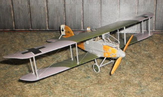
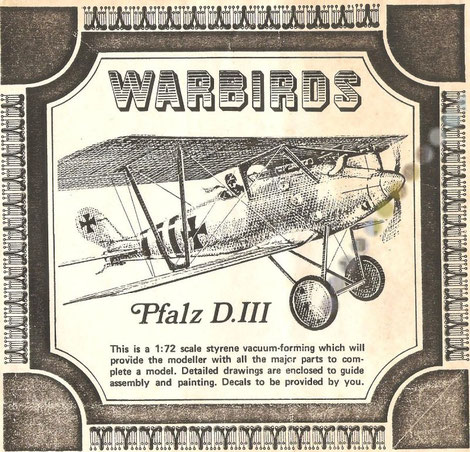
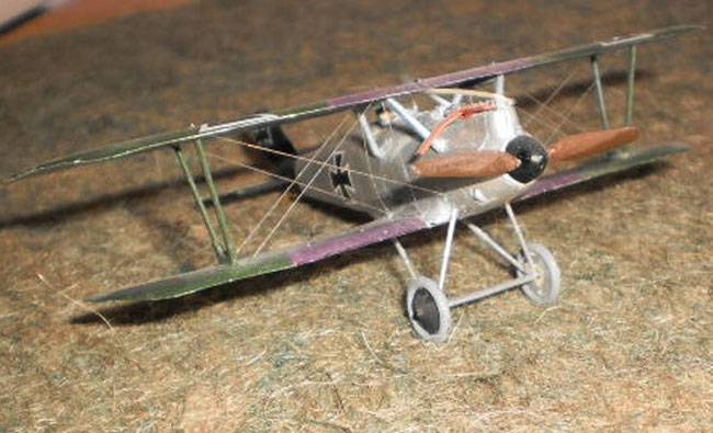
Building the Pfalz 111 by Rareplane Vacforms
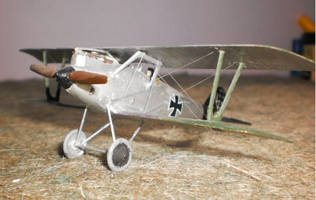
Build by 'Steve100'
History
The Pfalz D111 appears to have first flown in the spring of 1917. It underwent acceptance tests in June and was accepted for production, entering service with Bavarian Jastas in August. It was powered by a 160 hp Mercedes and the machine guns were located beyond the pilot’s reach under the forward cowlings. By the end of the year there were 276 D111s at the front but the improved D111a was now in production and there were 114 in service. In this model a higher powered Mercedes of 175/180 hp was installed, the guns located within reach, the lower wing tips became more rounded and a larger tailplane was added. In April 1918 there were 433 at the front and the Pfalz served within the ranks of 46 Jastas. As late as August 166 remained on active service. Allied reports of a captured example were praiseworthy and several aces flew the type with success.
Kit
This is a Rareplanes model that came out under the Warbirds banner. It has single surfaced wings, that is one piece, with fine upper surface detail. This includes a radiator and panelling and very fine ribbing and control horns. The under surface had to have the ribs and the other details scribed. As with most other kits, the fuselage is in two halves and there is a separate stabilizer/elevator. The moulding includes an engine, propeller, spinner, struts, undercarriage and wheels but with one exception these are of little use. Not that that stopped me trying to use them way back then. Originally built in the early 80s, the kit lay for many years in crashed wreck form in the spares box. It was my first vacform build and has since been refurbished and now stands proud alongside my more recent builds.
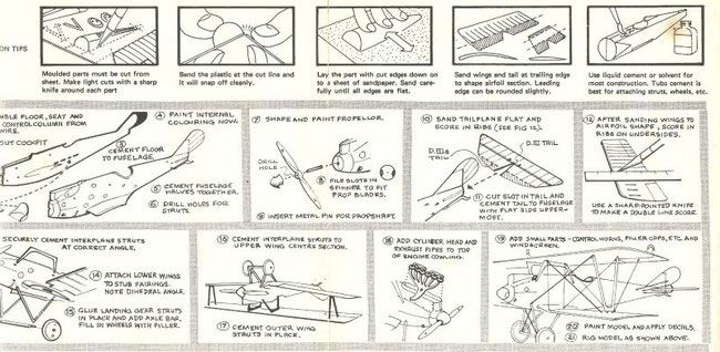
Instructions
Construction
First you have to cut the parts from the plastic sheet. When I did this, I used a carpet fitter’s Stanley knife and I used the point of the blade to make a series of small cuts around the part. This usually had to be repeated before flexing of the plastic would cause a parting in the plastic. When this happened the knife could be applied again and ran around the piece and remove it from the sheet. The knife was at 90 degrees and a lot of excess plastic remained on the part. More recent research has shown a better way which I now use. With this method you first draw around the part with a thin tipped marker and then follow the base of the line with the knife cutting at a 45 degree angle. This leaves less excess and the marker is your guideline as to how much you need to remove.
After all the parts you need have been removed, you have to remove any excess plastic as mentioned. Rubbing against wet and dry on a flat surface is usually recommended but I have a long flat file which produces similar results. In the case of the fuselage halves, you will have to open up the cockpit as this will be solid. A nick with a saw to guide a circular file works for me. Construction now begins as like any other short run kit. With this model you get a cockpit floor, with pedals moulded in, and a seat. Both are useable if you are going to crew up but others will want to use after market products or scratch. I painted the inside wood and installed a pilot. Then the halves were joined together, no problems. One thing I have noticed since is that the tail is thick. Both halves had a tail section and I think it would pay to remove them and install a scratch card unit.
The engine is all that remains to do on the fuselage. Rareplanes moulded the cylinder heads into the sheet and with care, they can be cut out, The exhaust and associated piping are useless but the heads can be used as the central part of the engine. I did not open up the engine top covers so I could cement the heads onto it. The portside manifold pipe work came from the engine of an Airfix Hannover that had been modified for use elsewhere. The exhaust was filed from card and fine plastic rod from Contrail provided the manifold pipes. Another alternative would be to open the top up and fit an engine from another kit or an aftermarket one from Aeroclub, for example. My worry about a metal engine would be the weight. This is a light kit and may become too nose heavy. But this is out of sequence. The exhaust and pipe work are left to the end because you know what will happen to it if it’s done now.
The engine is all that remains to do on the fuselage. Rareplanes moulded the cylinder heads into the sheet and with care, they can be cut out, The exhaust and associated piping are useless but the heads can be used as the central part of the engine. I did not open up the engine top covers so I could cement the heads onto it. The portside manifold pipe work came from the engine of an Airfix Hannover that had been modified for use elsewhere. The exhaust was filed from card and fine plastic rod from Contrail provided the manifold pipes. Another alternative would be to open the top up and fit an engine from another kit or an aftermarket one from Aeroclub, for example. My worry about a metal engine would be the weight. This is a light kit and may become too nose heavy. But this is out of sequence. The exhaust and pipe work are left to the end because you know what will happen to it if it’s done now.
Next are the wings. My first attempt at cutting had left plastic from the sheet on the undersides of the leading edges. This I now rectified as best I could and re-scribed the rib lines that were removed. I painted the wings at this stage. The lower wings are butt jointed to the fuselage and should be supported while the cement is drying. I let ordinary glue go tacky before joining and then set the kit onto some cardboard. When the wings are at the right angle, it is left overnight. Next morning. I reinforced the joints with CA after applying a little filler onto the underside joints. Before attempting the top wing, a windscreen was added curtesy of the spares box and Roden's Gotha G111. Machine guns weren’t needed as this is a D111 and they are enclosed. In its previous incarnation. I had added guns but they had been removed leaving a hole which was treated with filler.
The lower wings have impressions to indicate the position of the struts but I consulted photographs in several publications before I cemented anything in place. The kit struts are hopeless. They can be cut from the sheet but they are hollow on one side. I had filled them with polyfilla but they were overscale and looked terrible. So I looked to Contrail but the kit interplane struts have the correct angles moulded into them and the U shape within the base. Any side view will show you what I mean. I cut off the bases from the legs after filing them to match the thinner Contrail sections and joined them together. Left to consolidate, they turned out solid and useable. Tacky glue was used to get them into position on the lower wing followed by a few dry runs with the top wing and then they were CA’d into final position. The cabane struts are original, complete with original polyfilla, but filed as thin as I dared without breaking them. As I no longer possess any instructions frequent reference was made to photographs.
The tail elevator is moulded as a Pfalz D111a tailpiece. This is larger than the earlier D111 and is cut to shape. Again photos showed what was needed.
By now, I had also painted the fuselage and coated it with satin varnish to enable handling. With all the joints reinforced with CA, it was quite a sturdy little beast. Now the undercarriage had to be tackled. The kit version was the same as the rest of the struts etc. and was discarded. I used some leftovers from a Gotha G111 from Roden. The parts designed to prevent nose overs on landing proved very useful. After a bit of pruning, they were matched up with a section of aerofoil strut as the spreader bar and wheels from the spares box.
The prop spinner is useable and was cemented in place. Blades from the spares box completed the unit. Next came the rigging. Wings only as usual and it went quite well. I did notice that with the softer plastic the CA seemed to acquire a faster and firmer hold but this may be my imagination.
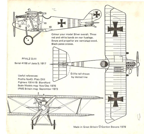
Colour Schemes
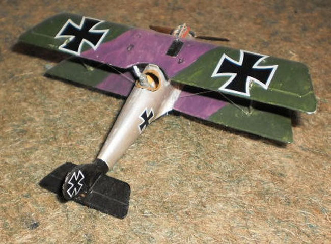
Pfalz aircraft mostly left the factory sporting a silver colour which was called silbergrau. When they reached the front line units, they were treated to the squadron markings and pilot’s preferences. Sites such as the Aerodrome and Cross and Cockade will be able to help in looking up numerous colour schemes. For this particular model, I painted the fuselage silver up to the tail unit which is black. The wing upper surfaces are painted purple (Humbrol 68) and green (3xRevell 48 to 1x 65). A Pfalz D111 of Jasta 10 had all its upper surfaces painted thus with the under parts silver and other DIIIs from the early production batch sported terrain camouflage on the wing upper surfaces. Many later DIIIa machines sported five colour lozenge. Mine doesn’t represent any particular machine but the black tail and spinner unit markings are representative of machines that flew with Jasta 16.
Decals
None with the kit. These came from the Almark A29 sheet of German Crosses Eiserne Keruz 1916-17. They are very good but you have to cut very closely around the cross to prevent a large section of transparent backing becoming part of the transfer.
Accuracy
Spot on. Wingspan was 30ft 10 ins, kit is 5.1 ins. Length was 22ft 93/4 and the kit is 3.8ins and height was 8ft 10 ins and the kit is 1.5 ins.
Recommendation
I have only seen the Roden kit as a preview and it certainly looks the part. There are other company offerings in injection and I’m sure they are all far superior to this vacform. But as far as this kit is concerned, the detail on the upper wings is good and the fuselage moulding also contains cockpit coaming, foot step, engine panels and what I think are cooling flues. It also offers the choice of a DIII or DIIIa version. I enjoyed myself, what more can I say.
References
Google on www.donsmodelworks.com and when you have the home page, click on references. Look for hints and tips and you get a pretty thorough lesson on vacform building.
A guide for vacuform kits by Diego Fernetti. www.wwi-models.org/misc/vacs.html
This site lists past and present manufacturers and their products.
The German Army Air Service in WW1, Vintage Warbirds No2 by Ray Rimmel. Plenty of photographs. ISBN 0-85368-694-7
Building the Phoenix D1 by Airframe
Build by 'Steve100'
History
The Phoenix D types were the end result of various experimental craft that had been designed to improve upon the Hansa Brandenburg D1 Starstrutter then in service with the Austro-Hungarian airforce. Manufacture began in August 1917 and the D1 entered service in December. Initially used as a fighter escort for two seater recce planes, it later was supplied to the true fighter squadrons. Over 70 remained in service during August 1918. The D11 began production in March 1918. It was lighter in an attempt to improve performance with 48 ordered. The D1 and D11 were both powered by the 200hp Hiero engine. The D11a received the 230hp version which gave much improved performance. If given the choice, most fighter pilots preferred the Albatros D111, but the D11a was apparently highly regarded. The further improved D111 was too late for the hostilities but an order for Sweden was completed after the war.
Kit
This is a vacform by Airframe. According to Windsock Datafile 31, the company is from Canada and this kit appeared in 1972. In the late seventies or early eighties, it cost £1.65. The plastic is white and the moulded parts are thinner than Rareplanes, for example.
Instructions
Too many memory cells have succumbed to the ravages of time and life. They must have been adequate but I can’t even remember what colour they were.


Construction
I began my vacform journey with the Pfalz D111 and my efforts could be described as how not to do it. This theme will be continued. First, we must cut out the parts from the sheet. I did a better job this time than the Pfalz. Memory defeats me as to all the parts that were moulded but I used the fuselage halves, elevators, upper wings and the upper wing radiator which is simply an oblong box. The rest came from the spares box, in particular Airfix’s Hannover.
The cockpit has to be cut out and filed to size. Detail as you want but there won’t be much to see even without the pilot. The seat came from the spares box, plus pilot, and the fuselage halves joined together OK. A touch of filler was used on the under surface join and a little was needed on the nose.
The wings are double surface, that is, they have upper and lower halves and the lower were fitted into the upper. They went together well and were finished off with a bit of filler. The trailing edge is considered to be too thick by modern standards. Using the top section only would require scoring the rib detail on the under surface but to me, the wing would be too flimsy judging by the surviving lower wing I still have. The plastic is fairly soft and I doubt I would be able to replace any detail I lost if I had filed my wings thinner so they remain as the instructions stated. Besides, they don’t look bad to me and with this kit, the lower surfaces have ribs incorporated which meant no ribs had to be scored or replicated with stretched sprue.
I didn’t like the lower wings as they were too flimsy if used in single surface mode and too thick when combined. The surviving section suggests poor assembly was probably as much to blame as any failing in the kit. So I replaced them with the lower wings from an Airfix Hannover. Back then, I was even less particular and did not notice the slight cut outs at the wing roots or that I hadn’t filed off the extra riblets along the leading edge. To be honest, I only noticed very recently when I decided to try and improve on my earlier efforts. However, they did make for a far sturdier construction and the small cut outs could be filled with plastic card quite easily.
The engine came from the Hannover, minus the exhaust and portside pipe work. The Phoenix fighters used the Heiro engine which exhausts to the left. I used stretched sprue but thin rod would do the job and they are stuck to the side of the engine block. Without the benefit of Windsock, my exhausts do not have a sufficient bend downwards. Because of this, my last pipe sticks out over the cabane struts instead of under. Over the years, it did bug me to the extent I was going to replace the pipes, but I recently found a photo in WS of the prototype DII that had a similar exhaust layout to mine. The old Profile publication has a photo of a naval DIII with the same layout so, being an idle chap, it was easy to convince myself that a field repair late in the war had been carried out on this DI as I would probably have wrecked it trying to get at the back pipes anyway.
The interplane struts came from the Hannover. Those on the D1 lean in over. The cabane struts are stretched sprue but today I would probably use Contrail struts. The stabilizers are double surface and definitely need filing to give a finer leading and trailing edge but aren’t too bad for thickness. The alternative is to use only one piece. The choice is yours.
Tail struts are made from sprue or rod, as are the undercarriage struts. Wheels and spreader bar came from the spares box and the propeller from the Hannover.
The radiator is an oblong cut from the moulding, faced by a thin piece of plastic card which was scored to look like a radiator grill. It should tilt forward when positioned on to the wing leading edge. The radiator fill cap is a tiny piece of rod. It must be situated on the starboard side of the radiator if a D1 is to be built. The pipes from the radiator to the engine are fine rod as is the engine manifold. The guns are concealed under the upper decking and are represented by similar rod protruding from two fine drill holes in the nose below the engine block. The windscreen is from the spares box. Finally, the D1 has a headrest which neither of the succeeding models carried. I snipped a small piece from the fuselage with a pair of nail clippers and substituted a headrest made from filed sprue. The rigging was done with Aeroclub invisible thread.
Colour Schemes
I can’t remember any schemes coming with the instructions. I based my original painting on a Hansa Brandenburg D1 in Munson’s Fighters 1914-19. Since then, Profile Publications and Windsock Datafiles have offered more recent research which shows mottled schemes that are beyond my current painting skills but aren’t that much different from the original interpretation.
Decals
There are none with the kit. I’m not aware of any specialist offerings but they’re probably out there, particularly the more colourful Austrian navy versions. This kit received crosses from Almark and the letters came from leftovers from a Matchbox Heyford. These are not aircraft specific but are based on the methodology of the time.
Accuracy
The shape looks OK to me and sizes up quite well to the plans in Windsock. The upper wing spans out at 5.4 ins, or 137mm, which is only a few scale inches out and the kits original lower wings are spot on. However, there are a couple of discrepancies. The kit is supposed to be a D1 but the fuselage has no headrest which makes it more like a D11 but that is easy to rectify. The upper wing is the right shape for a D1 but the elevators have one rib too many. The stabilizers are correct for a D1 but the tail fin/rudder is double surface and is too thick. If building again, I would remove it and replace with plastic card.
Sources
Windsock Datafile 31, Phoenix D1 – 11 : Peter M Grosz
Profile Publications The Phoenix Scouts No 175
Blandford Fighters 1914-19 : Kenneth Munson
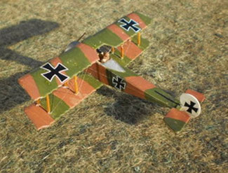
Siemens Schukert D111 by Airframe


History
Siemen’s first fighter was the D1, almost a copy of the Nieuport Bebe fitted with a Siemens 9 cylinder rotary. The company continued development of rotary engines and by mid 1917, was flying aircraft powered by a new 11 cylinder engine delivering 160hp. From these aircraft were developed the D111 and DIV fighters which in regards to manoeuvrability and rate of climb, became the German equivalent to the Sopwith Camel. First deliveries of the D111 were made in January 1918 and the type appears to have become operational in May. The early engines proved prone to overheating and the aircraft were returned to the factory. Here they received the new 200hp model and the fully enclosed cowlings were modified to assist cooling by cutting away the lower section.
From July onward, they served with Jastas 2, 12, 13, 15, 19, 26, 27 and 36. They also flew with five home defence Kesta and some were retained by training schools. Eighty D111s are believed to have been built and they were followed into production by the DIV. This had narrower chord wings and entered surface in August. About 120 were delivered before the war ended and half of these reached the front where they are known to have flown with Jastas 11, 14 and 22. The DIV was faster and climbed even better than the D111 and was regarded as the best single seater at the Front by one fighter ace in October 1918.
The Kit
This is a vac form from the seventies / early eighties. It is the usual white plastic sheet and items such as struts, undercarriage legs, prop and engine were of little use. The fuselage halves, double surface wings, tail/rudder, elevator/stabilizer were used. The engine cowling is full and the only other parts used were the headrest and the axle bar.
Instructions
They comprise exploded views but it is such a long time since I saw them I can’t comment further. Adequate is the word that springs to mind.
Construction
This was a fun project. I have always had a soft spot for this series of aircraft but have never seriously sought to obtain an injection model. It too has lain as a crash victim for many years.
As usual, the parts intended for use are cut from the plastic sheet using a sharp knife of your choice held at about 45 degree angle. A marker or pencil drawn around the part will let you know how much excess plastic needs to be filed off. Score lightly around several times so you can flex the part from the sheet. Remove excess and now it is just another short run kit requiring a good spares box and some aftermarket parts.
The fuselage has a U-shaped former within the cockpit area when the parts are put together. This adds strength to the kit and gives a surface to set a floor on, or just a seat from the spares if a pilot is fitted. The upright bar in front of the pilot can be utilized. I added a dial from rod and others can be stuck on the cockpit sides as I believe the SS D111 did not have a formal instrument panel. The seat came from the spares box and a pilot was added. It is quite a roomy cockpit so a pilotless example can be detailed to the modeller’s own standards. The halves are then brought together. I didn’t use tabs originally but the joins aren’t too bad. Filler was used and I gave the joints the final filing they had missed years ago. The headrest had also been added.
My original engine had been from an Airfix Camel but this was removed and replaced by an Aeroclub eleven cylinder Siemens rotary. The cowling had been fitted as full so I cut away the lower section in order to remove the old engine and position the new. Using references from other sites, I shaped the upper section to match before using
CA to glue the 11 cylinder piece in place. Then the open lower section was constructed using 10 thou. card and plastic rod.
The fuselage lacks panel lines so these need to be scored with a sharp knife. I used photos of completed models from other sites as a reference. However, the bulged cooling vents (?) in the front section are part of the moulding. These are reduced in size and a hole is drilled into the front. More vents are moulded into the underpart of the nose section and these are highlighted with metal paint. Final addition to the fuselage was a pair of Spandaus that came from the spares. I incorporated a windscreen into the rear butts based on a photograph I have seen.
The wings are double surface and I glued the lower into the upper wing. Rib detail is fine on the upper but needed to be scored on the lower with a sharp knife. The gaps were filled and all attempts to reduce the edges were limited to the lower surfaces. I don’t like removing detail as I find it hard to replace, so I filed the lower edges until they were level with the upper. I’m happy with the leading edges but the trailing edges will be regarded as too thick by the purists. What I am not happy about is that the starboard lower wing has become misformed. From the fuselage, it has anhedral then goes to dihedral. It has become warped. Attempts to straighten it failed so rather than break the only wing I had it was left alone.
The stabilizer is double surface and isn’t much thicker than a Revell DV11 or Airfix DV offering. The rudder is likewise and is too thick. The upside is that both sides have ribbing incorporated. The rudder is also the later square shape which can be filed down to an earlier more rounded type.
The wing struts came from the spares and the cabane were stretched sprue. Before the wings were attached, they were treated to a covering of five colour lozenge and the fuselage painted as natural wood. Tail, rudder and cowling were decorated and then the lower wings were attached followed by the upper. Believe it or not, but the cabane struts had actually survived the crash wreck stage and one set remained attached to the fuselage and the other to the upper wing. They were checked for alignment, proved OK and then attached prior to being left overnight in a card support based on the Airfix Pup design.
The undercarriage is plastic rod and the axle spreader bar is from the kit with the hollow filled with pollyfilla. Wheels from the spares were used and the four blade prop was cut down from a spare that originated from the Airfix 0/400. Tail skid is rod and the rigging is invisible thread.
Colour Schemes
There will be numerous different schemes based on the different Jasta colours during 1918. Make one up like I have or do the research if you want a particular machine. The wood finish is Humbrol Matt 62. The struts and undercarriage legs are grey Revell 43 and the blue is Humbrol Matt 25. All parts except the various struts were treated with a coat of satin varnish which is Poly Vine acrylic enamel.
Decals
These are Almark Balkan Keruz 1918 and the numbers came from the earlier cross sheet. The lozenge is also Almark, A33 five colour upper surface and A34 five colour lower surface. I experienced little difficulty with them.
Accuracy
This is pretty much spot on. Span is 4.6ins which equates to 27ft 7ins and is exactly right. Length is 3.1ins which is 18ft 7ins and is just under two scale inches short while the height is 1.6ins, a scale 9ft 7ins or a scale 4ins too high. I can’t complain about that. However, there are reviews of the Toko D111 that mentions differences of chord width in the upper wing. My researches on other sites suggest that the various kits of this type all have narrower upper wings than this vacform. I haven’t gone into any great detail but according to Munson, the narrow wings were fitted to the D1V version. If the Toko D111 has narrow wings, then I am going to suggest that the Airframe kit represents one of the early batches which were delivered with fully cowled engines. These were returned to manufacturers in the early summer of 1918 to be refitted with more powerful engines and revised, more open cowlings. I have read somewhere that many of these machines were then sent to the home defence Kestas to combat the Allied bomber raids.
Recommendations
As usual unless an injection kit has hideous accuracy levels, go for it rather than a vacform. That said this version does not appear to be covered by those manufacturers. It has to be very hard to find nowadays but it makes a nice little kit. It was an enjoyable build.
Sources
Fighters 1914-1919 : Kenneth Munson (1968)
The German Army Air Service in WW1 ; RL Rimell (1985)

